產品中心
有任何問題
立即聯系我們!
027-86633356
Sales@fiberhtt.com
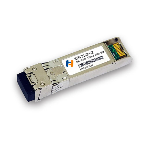
| 型號: | HSFP3128-SR |
| 封裝類型: | SFP28 |
| 速率: | 25G |
| 傳輸距離: | 300m |
| 波長: | 1310nm |
| 溫度: | 0°C to 70°C, -40°C to +85°C |
| 定制化: | 提供定制化服務 |
HSFP3128-SR transceivers support the 2-wire serial communication protocol as defined in the SFP+ MSA.
The standard SFP serial ID provides access to identification information that describes the transceiver’s capabilities, standard interfaces, manufacturer, and other information.
Additionally, FiberHTT SFP+ transceivers provide a unique enhanced digital diagnostic monitoring interface, which allows real-time access to device operating parameters such as transceiver temperature, laser bias current, transmitted optical power, received optical power and transceiver supply voltage. It also defines a sophisticated system of alarm and warning flags, which alerts end-users when particular operating parameters are outside of a factory set normal range.
The SFP MSA defines a 256-byte memory map in EEPROM that is accessible over a 2-wire serial interface at the 8 bit address 1010000X (A0h).The digital diagnostic monitoring interface makes use of the 8 bit address 1010001X (A2h), so the originally defined serial ID memory map remains unchanged.
The operating and diagnostics information is monitored and reported by a Digital Diagnostics Transceiver Controller (DDTC) inside the transceiver, which is accessed through a 2-wire serial interface. When the serial protocol is activated, the serial clock signal (SCL, Mod Def 1) is generated by the host. The positive edge clocks data into the SFP transceiver into those segments of the E2PROM that are not write-protected. The negative edge clocks data from the SFP transceiver. The serial data signal (SDA, Mod Def 2) is bi-directional for serial data transfer. The host uses SDA in conjunction with SCL to mark the start and end of serial protocol activation. The memories are organized as a series of 8-bit data words that can be addressed individually or sequentially.

HSFP3128-ER
SFP28 25G 1310nm 40km

HSFP3128-LR
SFP28 25G 1310nm 10km
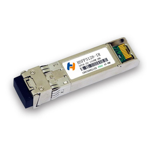
HSFP3128-IR
SFP28 25G 1310nm 2km